What Is StarFish?
StarFish are a range of side-scanning sonar systems that use the latest acusotic technology and signal processing techniques to bring you high quality underwater imagery at affordable prices.
All the systems have been specifically designed for single-person deployment and shallow water survey in water depths up to 30m/100ft, making them ideal for port & harbour survey & security work, inland water survey of rivers/canals/lakes, wreck location and Search and Recovery (SAR) missions.
 StarFish towed systems are extremely portable, with each sonar less than 15" long. This enables them to be easily shared between groups of users or vessels when required, and excel in remote shallow water locations where other side scan systems struggle to perform.
StarFish systems have been designed to be 'plug & play', connecting to your PC/laptop via a top-box with USB connection. The topbox allows the sonar to be powered from both AC (i.e. mains supply) or DC (i.e. battery, generator) sources and multiple adaptor cables are supplied with every system, making it straightforward to power the StarFish system from your existing power source.
The intuitive StarFish Scanline software, designed for Windows operating systems, has an easy-to-use interface. With helpful Wizards to get you started, you'll be up and running in no time.
So, What is a Sonar?
Sonar (SOund, NAvigation and Ranging) is a technique that uses sound waves to detect and locate objects underwater. Side scan sonar is a specific type of sonar used to image the topography of the seafloor.
Side scan sonar; also referred to as side-looking sonar and side-imaging sonar; is often towed from a survey vessel and has the ability to capture hundreds of metres of seafloor on each side of the moving vessel. The near photographic quality images produced by side scan sonar along with its ability to map large areas of seafloor quickly make it an essential piece of kit for anyone requiring high definition images of the seabed.
Side scan sonar is used extensively for many commercial, military and leisure applications. Some examples include search and rescue operations, pipeline and cable route surveys, mine detection, fish finding, wreck hunting, recovery of drowned victims, marine archaeology and geological surveys.
How Does a Side-scan Sonar Work?
Side-scan sonars transmit a narrow fan-shaped acoustic pulse (ping) perpendicular to its direction of travel. As the acoustic pulse travels outward from the side scan sonar, the seabed and other objects reflect some of the sound energy back in the direction of the sonar (known as backscatter). The travel time of the returned pulse is recorded together with its amplitude as a time series and sent to a topside console for interpretation and display. The topside console stitches together data from successive pulses, creating a long continuous image of the seafloor as the side scan sonar is towed from a survey vessel.

The numbers on the diagram represent...
- Depth to inside of acoustic path.
- Vertical beam angle.
- Range setting in software (maximum acoustic range).
- Swath width accross seafloor.
- Tow depth of side scan sonar.
- Port and starboard channel separation.
- Horizontal beam width.
Interpriting Sidescan Images
As with any acoustic sonar, side scan sonars only show echoes of objects that reflect sound back to the side scan sonar transducer, such that hard shiny surfaces are sometimes only seen when they are at right angles to the sonar and rough seabed textures can blot out smaller targets completely.
Materials, such as metals, boulders, gravel or recently extruded volcanic rock, are very efficient at reflecting acoustic pulses (high backscatter). Finer sediments like clay and silt, on the other hand, do not reflect sound well (low backscatter). Strong reflectors create strong echoes, while weak reflectors create weaker echoes. Knowing these characteristics, you can use the strength of acoustic returns from the side scan sonar to examine the composition of the seafloor and any objects which may lay on it.
The diagram below to shows how a typical sonar scanline is built from the strength of acoustic returns to the sonar.

- Depth to inside of acoustic path.
- Vertical beam angle.
- Range setting in software (maximum acoustic range).
- Swath width accross seafloor.
- Acoustic shadow length, corresponding to height of target.
- Area before first "bottom" return (no sound = black).
- Seabed texture.
- Very reflective corner of object (brightest intensity).
- Reflective object (target).
- Acoustic shadow of target (no returns in here!).
- Seabed texture.
Interpretation of side scan sonar data develops with experience. Side scan sonar reflections of isolated small objects give no indication of shape or attitude. Man made structures, such as platforms or rock walls tend to have regular patterns that are easier to identify.
Using a side scan sonar is rather like looking at a world made of shiny black plastic, in the dark, with only a narrow torch beam for illumination. Remember that when close to large objects, or in a depression in the seabed, that the viewing range of the side scan sonar may be severely limited.
Very strong reflectors may give multiple echoes along a bearing line, and are identified by being equispaced in range. The plan view provided by the side scan sonar also does not show how high an object is, unless an acoustic shadow is cast, in which case the length of the acoustic shadow is related to the height of the object, its range, and the height of the side scan sonar.
The "Chirp" Signal Advantage
CHIRP (Compressed High Intensity Radar Pulse) techniques have been used for a number of years above the water in many commercial and military RADAR systems. The techniques used to create an electromagnetic CHIRP pulse have now been modified and adapted for acoustic imaging sonar systems. StarFish uses CHIRP techniques at the core of its acoustic engine.
Monotonic Sonar Operation
To understand the benefits of using CHIRP acoustic techniques, we need to analyse the limitations using conventional single frequency (monotonic) techniques. An acoustic pulse consists of an on / off switch modulating the amplitude of a single carrier frequency.
The figure shows how this relationship exists between the transmitted signal and the outputted produced by the receiver circuitry in the sonar. It can be seen that the receiver does not decode each cycle of the transmitted pulse, but instead produces the "envelope" of its overall amplitude...

The ability of monotonic acoustic systems to resolve targets is better if the pulse duration is short; this, however, has its drawbacks. Ideally, we need long transmit pulses to get enough acoustic energy into the water for good target identification of the furthermost targets, but due to the velocity of sound through water ("VOS" - typically around 1500 metres/second), each pulse will occupy an equivalent "distance" related to its pulse duration – this is referred to as "range resolution", and can be given by the following equation...

For example, in conventional monotonic side scan sonar systems the pulse duration is typically 100 micro seconds, and combining this with the typical VOS, a range resolution of 75mm is obtained.

The "range resolution" effectively determines the ability of the sonar to identify separate targets; so, using the example above, if two targets are less than 75mm apart then they cannot be distinguished from each other. The net effect is that the system will display a single large "combined" target, rather than multiple smaller targets, and any fine sonar detail is lost. Chirp signal processing overcomes these limitations!
Chirp Sonar Operation
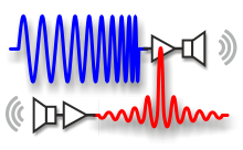
Instead of using a pulse of a single carrier frequency, the frequency within the burst is changed (swept) through the duration of the transmission, from one frequency to another. For example, at the start of the transmission the sonar may operate at 100KHz, and at the end, it may have reached 150KHz – the difference between the starting and ending frequency is known as the "Bandwidth" of the transmission, and typically the centre frequency of the transmission is used to identify the sonar (in this case it would be a 125KHz sonar).
By constantly changing its frequency over time, this "chirped" transmission can be thought of as having a unique acoustic signature, and so if two pulses now overlap (as the targets are closer than the range resolution), we can use the known "frequency versus time" information to tell them apart.
With modern high-speed digital-signal-processing (DSP) techniques, the StarFish sonar receiver contains a "pattern-matching" circuit that looks for its transmitted "CHIRP" being echoed back from targets, and its receiver now produces a sharp ‘spike’ when a good match is found (whereas the monotonic sonar that produces an output the same duration as its transmit pulse)...

This means that the critical factor in determining range resolution is no longer the pulse length, but the bandwidth of the CHIRP, so the range resolution can be found by...

Expanding on the previous example, the bandwidth of the StarFish CHIRP system is typically 40kHz, and using the same VOS of 1500 metres/second, our new range resolution is 18.75mm... a theoretical improvement by a factor of 4 over the monotonic example above!

This figure above shows that on a chirped sonar, when two acoustic echoes overlap, the CHIRP pulses do not merge into a single acoustic return (as their frequency is different from each other at the overlapping points), and the sonar is able to resolve and display the two targets independently.
Therefore, we now can have longer transmissions (and see targets further away) without a loss in resolution; and additionally, CHIRP signal processing techniques offer improvements in background noise rejection (as the side scan sonar is only looking for a swept frequency echoes, removing random noise or out-of-band noise).